Hardware Design
Mechanical Design
The Pololu Romi chassis is a circular robotic platform with a 6.5” diameter. It uses two 70 mm wheels driven by 120:1 mini plastic gearmotors with integrated quadrature encoders, and a rear ball caster for stability. Power is supplied by a six-cell AA battery pack, and the chassis includes a wide range of mounting holes compatible with common fasteners. Several custom components were developed for this project, including a 3D-printed IMU calibration jig with front and rear pieces that allow the robot to stand upright on either end for accurate calibration of the BNO055 IMU. The IMU is mounted to the underside of the chassis using standoffs, with its Z-axis oriented vertically so that its Euler heading directly represents yaw. The QTRX-MD-07A 7-element reflectance sensor array is also mounted underneath the chassis using standoffs at approximately 5 mm above the ground. This height is critical because if too high, reflected IR signals weaken and adjacent sensor cones overlap, reducing contrast. If too low, the sensing area becomes too narrow and sensitive to surface imperfections, reducing measurement consistency and making line detection less reliable. The HC-SR04 ultrasonic sensor is hot-glued to the front calibration jig, positioning it at the forward face of the robot for effective obstacle detection.
Electrical Design
Wiring Diagram
Nucleo Pinouts (Left)

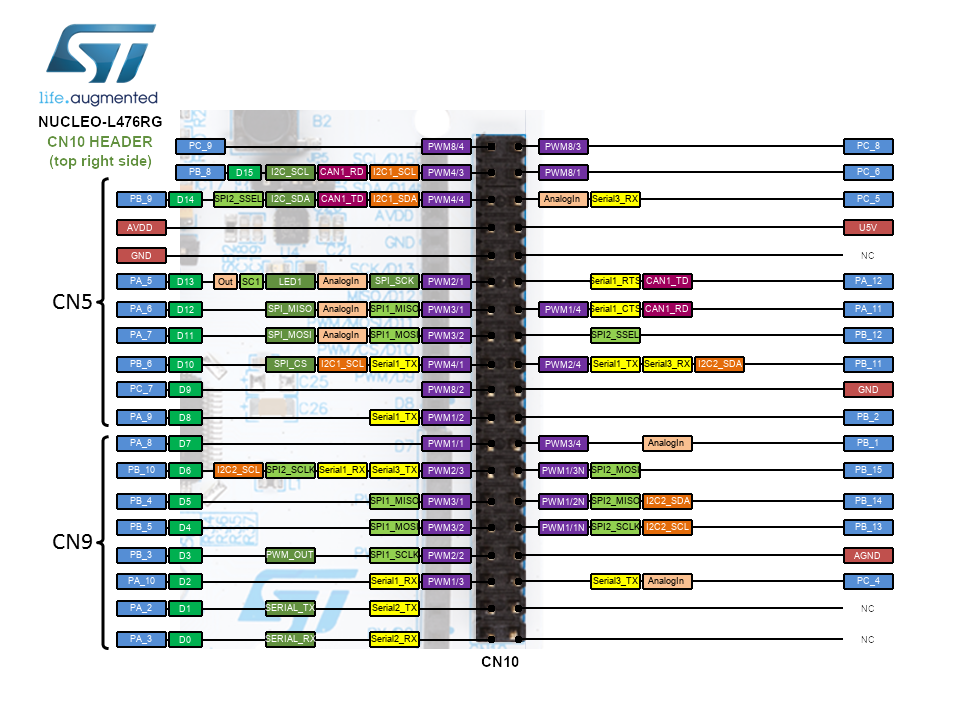
Nucleo Pinouts (Right)
Components & Pin Assignments
Component |
Interface |
Nucleo Pin(s) |
Notes |
|---|---|---|---|
Left motor |
PWM + GPIO |
A7 (Tim3 Ch2), B11, B12 |
PWM 50 kHz, direction, sleep/enable |
Right motor |
PWM + GPIO |
A6 (Tim3 Ch1), C7, B6 |
PWM 50 kHz, direction, sleep/enable |
Left encoder |
Timer 2 (QEI) |
A0 (Ch1), A1 (Ch2) |
Quadrature, 1437.12 counts/rev |
Right encoder |
Timer 1 (QEI) |
A8 (Ch1), A9 (Ch2) |
Quadrature, 1437.12 counts/rev |
Reflectance array (×7) |
ADC |
A5, C2, C3, A4, B0, C1, C0 |
Left-to-right pin order |
BNO055 IMU |
I2C2 |
B13 (SDA), B14 (SCL), B15 (RST) |
Addr 0x28, 100 kHz |
Ultrasonic sensor |
GPIO |
B3 (Trig), B4 (Echo) |
HC-SR04 |
Battery voltage divider |
ADC |
B1 |
4.7 kΩ / 10 kΩ, 12-bit, 3.3 V ref |
Power Supply
The robot is powered by a 6-cell AA battery pack (nominal 6.5 V). Motor drive voltage is derived directly from the pack; the STM32 Nucleo is powered via USB or its own onboard regulator. Battery voltage is monitored in real time through a 4.7 kΩ / 10 kΩ resistor divider connected to ADC pin B1 (12-bit, 3.3 V reference). The measured ADC voltage is scaled by a factor of (1 + 10/4.7) ≈ 3.27 to recover the true pack voltage, with a small empirical correction factor of 0.305 applied to account for actual VDD.